Recommend Procedure
- soldering the pinheader to the PlusCart breakout PCB
- soldering the ESP8266 to the PlusCart breakout PCB
- shorten the ESP8266 pins with a side cutter (so the STM32F407VGT6 breakout board fits in)
- triple check the ESP8266 soldering pins with a magnifier!
- soldering the STM32F407VGT6 board to the PlusCart breakout PCB (check that the ESP8266 pins have no contact to the STM board!)
- soldering the pinheader for boot0 and boot1 to the STM32F407VGT6
- short boot1 (with a jumper or by soldering)
- then flashing the current firmware to the STM32F407VGT6

Pins of the ESP8266-01 have to be clipped down with a side cutter after soldering:
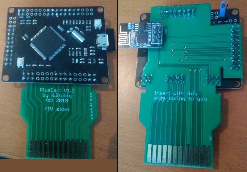
BOOT1 on the STM32F407VGT6 breakout board has to be short for flashing and can be short during operation. This can be done with a jumper or by soldering:


